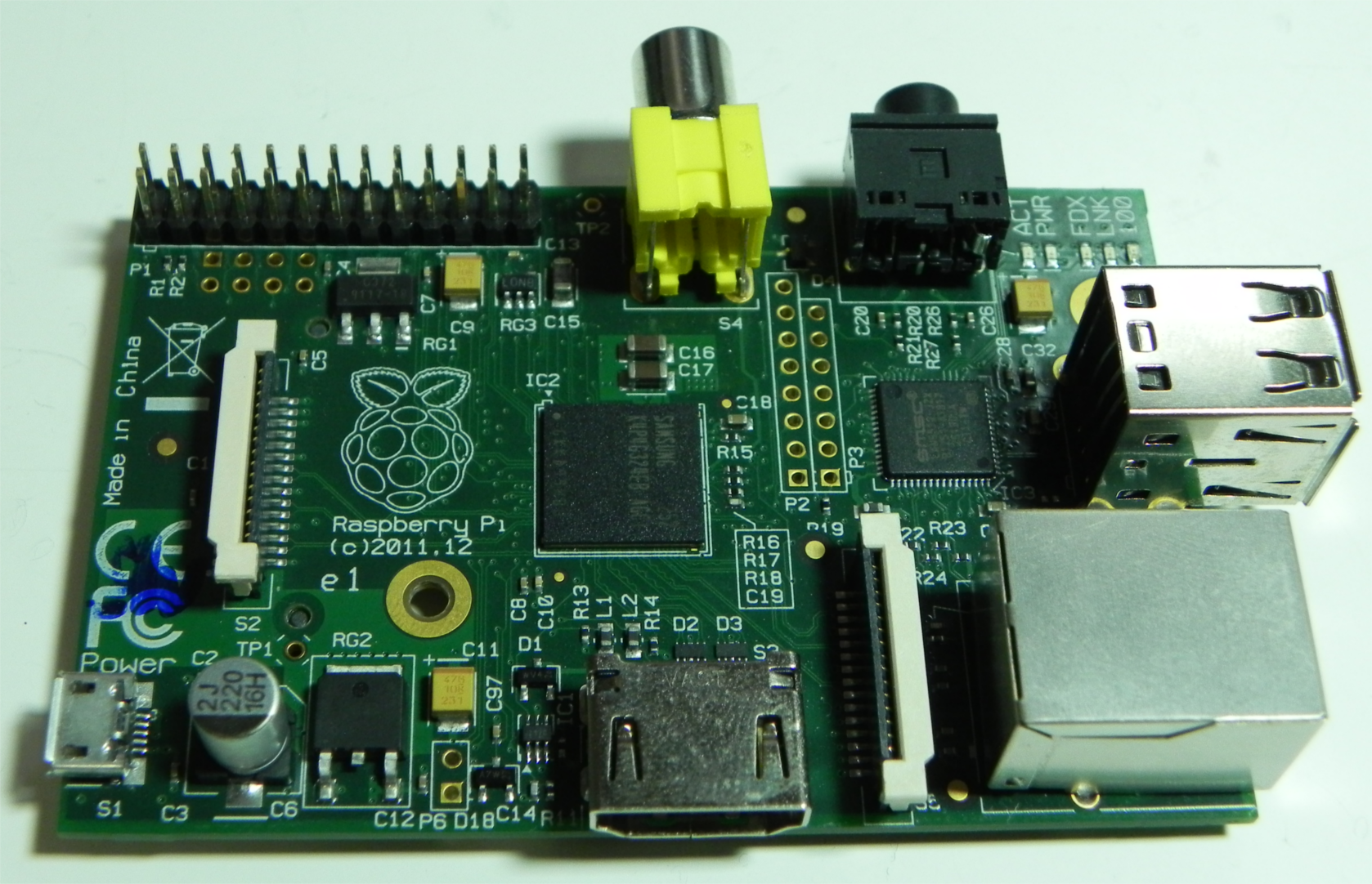
Raspberry Pi Kernel
A Journey Awaits
This is the story of how I implemented an operating system in assembly. My motivation was to learn how modern programming languages and operating systems were related to the underlying binary. Until this point, I had only learned Python and Java, I was just starting C (and really hating pointers and segfaults), and I was confused about how high-level concepts like Objects, were translated down to 1’s and 0’s that the CPU could actually use.
The work was done as a directed study in my second year under the supervision of Dr. Yvonne Coady.
This post is brought over from my original university page, which may or may not remain in existence for much longer, as I am graduating. Unfortunately, a lot of the content appears to be missing, since I’ve also since updated my university page a few years back. I’ll do my best to piece together the parts. For the most part, this will be in past-tense since it is my recollection.
I am attempting to write the underlying components of an operating system for the Raspberry Pi, using the ARMv6 assembly language for the ARM1176 processor.
Starting out was quite difficult. There were three main challenges that I had to overcome;
- Learning ARM assembly
- Find and read the documentation on the ARM 1176JZF-s chip that was in my device
- Construct a toolchain and workflow to actually get things to work
Rough Seas Ahead
I started out by trying to get something that would assemble, and also by following various tutorials.
After learning a bit of ARM assembly, I decided to get to the point where I could assemble something.
@This is a quick test source for my building process for ARM
    .text
    .global _start
_start:
    mov sp, #0x8000   @Set stack pointer to starting position
    mov r1, #42       @Move literal word 42 into register 1
    swi 0x11          @End program

    .data
    .end
At the time, I had a very simple bash script that would do the work of assembling and constructing the kernel image.
#!/bin/sh
compiler=arm-none-eabi
code=../code
boot=../boot
debug=../dbg

#First compile the code
$compiler-as $code/init.s -o $code/init.o

#Call the linker to generate the binary output

$compiler-ld $code -o $code/kernel.elf

#Show us the disassembled code for debuging
$compiler-objdump -D $code/init.o > $debug/init.disassembled.s
$compiler-objdump -D $code/kernel.elf > $debug/kernel.disassembled.s

#Now copy into an image format
$compiler-objcopy $code/kernel.elf -O binary $boot/kernel.img
Sadly, even though I was following tutorials, this stuff wasn’t working. I kept at the tutorials method until October 2nd. I ended up deciding to learn the stuff on my own by reading it directly from the manual. This took me the better part of October, lasting up until the 25th.
Return with Vengeance
After reading the documentation, I sat down again and hammered something out. My goal was to get access to the GPIO pins, and most importantly, the little green LED. Once I had access to that, I could communicate with the board and see that my code was doing something. In the meantime, I had also written a new setup for doing workflow stuff.
The new makefile:
1
2
3
4
5
6
7
8
9
10
11
12
13
14
15
16
17
18
19
20
21
22
23
24
25
26
27
28
29
30
31
32
33
34
35
36
37
38
39
40
41
42
43
44
45
46
47
48
49
50
51
52
53
54
55
56
57
58
59
60
61
62
63
64
65
66
67
68
69
70
##########################################
# Raspberry Pi Kernel Makefile
#
#   Author: Evan Wilde
#   Date:       October  25 2013
#   Updated:    November 20 2013
#   Modularized:December 20 2013
##########################################
#
# TODO: Update for handling .c files
#

TOOLS       ?= tools/
BOOT        ?= boot/
PREFIX      ?= $(TOOLS)/bin/
ARMGNU      ?= $(PREFIX)arm-none-eabi

LINKER      = kernel.ld

#Directories
SOURCE      = source/
BUILD       = build/
BOOT        = boot/
OUTPUT      = release
DEBUG       = debug


#Output Filenames
TARGET      = kernel.img
LIST        = kernel.list
MAP         = kernel.map

OBJECTS := $(patsubst $(SOURCE)%.s,$(BUILD)%.o,$(wildcard $(SOURCE)*.s))

all: $(TARGET) $(LIST)

rebuild: clean all

$(LIST): $(BUILD)output.elf
    $(ARMGNU)-objdump -d $(BUILD)output.elf > $(DEBUG)/$(LIST)

$(TARGET): $(OUTPUT) $(DEBUG) $(BUILD)output.elf
    $(ARMGNU)-objcopy $(BUILD)output.elf -O binary $(BUILD)$(TARGET)
    cp $(BUILD)$(TARGET) $(OUTPUT)/$(TARGET)
    cp $(BOOT)bootcode.bin $(OUTPUT)/bootcode.bin
    cp $(BOOT)fixup.dat $(OUTPUT)/fixup.dat
    cp $(BOOT)start.elf $(OUTPUT)/start.elf

$(BUILD)output.elf: $(OBJECTS) $(LINKER)
    $(ARMGNU)-ld --no-undefined $(OBJECTS) -Map $(DEBUG)/$(MAP) -o $(BUILD)output.elf -T $(LINKER)

$(BUILD)%.o: $(SOURCE)%.s $(BUILD)
    $(ARMGNU)-as -I $(SOURCE) $< -o $@

$(BUILD):
    mkdir $@

$(OUTPUT):
    mkdir $@

$(DEBUG):
    mkdir $@

clean:
    -rm -rf $(BUILD)
    -rm -rf $(OUTPUT)
    -rm -rf $(DEBUG)
    -rm -f $(TARGET)
    -rm -f $(LIST)
    -rm -f $(MAP)
The program itself
1
2
3
4
5
6
7
8
9
10
11
12
13
14
15
16
17
18
19
20
21
22
23
24
25
26
27
28
29
30
31
32
33
34
35
36
37
38
39
40
41
42
43
44
45
46
47
48
49
50
51
52
53
54
55
56
57
58
59
60
61
/*=============================================================
*   Author: Evan Wilde
*   Date:   October 25th 2013
*   Description: This program demonstrates basic access
*       to the OK LED on the raspberry pi, and the first
*       signs of life.
===============================================================*/
    .section .init
    .global Start

    .equ    ACTIV_LED, 0x20200000

Start:
    mov sp, #0x8000 @Setting stack

loop:
                            @Off Cycle

    mov r0, #0x500000
    bl delay
                            @Turn off OK LED
    ldr r0,=ACTIV_LED
    mov r1,#1
    lsl r1,#18
    str r1,[r0,#4]
    mov r1,#1
    lsl r1,#16
    str r1,[r0,#28]

                            @On Cycle

    mov r0, #0x500000
    bl delay
    ldr r0,=ACTIV_LED
    mov r1,#1
    lsl r1,#18
    str r1,[r0,#4]
                            @Turn on OK LED
    mov r1,#1
    lsl r1,#16
    str r1,[r0,#40]
    bal loop

/* === Delay ====================
*   A very dumb delay system, but
*       it works.
*   Input
*   r0: Delay length
*/

delay:
    stmfd   sp!, {lr}
delLoop:
    subs r0, r0, #1
    beq delLoopEnd
    nop
    bal delLoop
delLoopEnd:
    ldmfd   sp!, {pc}

    .end
The linker information
/*************************************************
* Kernel Linker Script
*
*************************************************/
SECTIONS {
    .init 0x8000 : {
        *(.init)
    }
    .text : {
        *(.text)
    }
    .data : {
        *(.data)
    }
    /DISCARD/ : {
        *(*)
    }
}
This time, it worked. It compiled, then I put it on the SD card and it booted right up. Video
This was great news. Yes, I essentially had the month of November remaining, since December was for finals, but I had something blinking. It was pretty rough, but I knew that things appeared to be working.
From there, I sat down and figured out how the framebuffer worked and learned a bit more about the architecture of the chip. Prior intuition told me that the CPU booted up and got everything going, starting the GPU in the bootup process. This was actually backward for this chip. The GPU was the first thing to boot, it loaded up the bootcode.bin and some other files. Once it was satisfied with all of this, it fired up the CPU, so the CPU was more like the peripheral processor to the GPU. That took a bit of time to wrap my head around. The CPU communicated with the GPU via a mailbox that would get checked when the GPU felt like it. I sat down and figured out how to get that to work.
My goal was to get colors on the screen. I wasn’t entirely sure how that worked. It was a bit past midnight when I finally got something to work. Unfortunately, it was a whole lot of bright flashy colors changing as fast as they could (and of course I had the lights off too). The results were beautiful. I called this version the “Rave OS” since it was kind of like how I imagine a rave party to be like. Video. But it was also kind of expected.
The next goal was to have control over the color space. My OS used a 16-bit colorspace. The first thing I noticed was that 16 doesn’t divide nicely into 3 (for the red, green, and blue channels). So I sat down and did more reading on how the 16-bit full color system works. It turns out that there are 5 bits of red, 6 bits of green, and 5 bits of blue. Interestingly, the choice to have the extra bit of green was intentional, the human eye is more perceptive to changes in green than to red or blue because it is right in the centre of the visible light spectrum. Once I understood how this all worked, I sat down and wrote a new kernel that would cycle through the color space. The first version had a few glitches around the points where it would need to start switching to the next channel. The color would jump from a lot of green, down to no green and some blue and then keep going. I think I had the ah-ha moment on how to transition through the full color space smoothly while I was in a meeting or something. Video
Then it was time to sit down and work on the actual keyboard stuff. Unfortunately, I’ve lost most of the video and files for this part, so no video. Anyway, I quickly learned about the intricacies of USB. Having been in electronics in high school, I had some fairly good intuition on how digital logic worked, but USB was a bit more clever than I was. USB has (had) four wires. My intuition suggested that one wire was for positive, one for ground, one for transmission, and the other for receiving. Kind of like how ethernet works. Nope, I was wrong. So my intuition on positive and ground were correct, but it turns out that data is a bit weird. Having one wire for transmission and the other for receiving actually incurred too many errors given the intended transmission speeds for usb 2.0. To get around this, the USB designers decided to essentially add a parity line. One data wire would go high if it was transmitting a 1, and the other wire would stay low. The Other wire would go high if it was transmitting a zero. By having the two lines used for transferring data simultaneously, USB could maintain the speed and resolve errors (both lines are high or low). Turns out, most of the stuff surrounding this is implemented in hardware (nice, less work for me). There was quite a bit of work to implement the stuff for USB though and it was quite difficult. I didn’t have the timers working correctly yet, so ensuring some of the properties of USB were held was next to impossible. I ended up writing a driver that was kind of partially compliant though. By partially compliant, it was able to work with one keyboard; no other keyboards would work.
Once I had the keyboard thing kind of sorted out, I wanted to be able to type commands and make the OS do stuff. I wrote out a font. It was pretty fun since I could make any shape I wanted. Being boring though (or useful), I stuck with normal characters for the most part. The bitmap font was essentially a bunch of random numbers, but they represented the patterns of 1’s and 0’s where 1 indicated foreground color, and 0 indicated background color. If I recall correctly, the bitmaps ended up being an 8x8 grid. The character ‘0’ might be represented as 0x0038444c54643800. This number by itself isn’t that useful, converted to binary it suddenly pops to life though.
00000000
00111000
01000100
01001100
01010100
01100100
00111000
00000000
I had the wonderful task of sitting down and drawing out all of the ascii characters. It was not that much fun, but it was cool to see how adjusting my font had a visible implication on how the character would look.
One thing I had forgotten about at this point was endianness though. Unfortunately, the basic font didn’t work because the endianness was different than what I was writing. Flipping the nibbles, I was able to get something that would work out.
Peaceful Seas
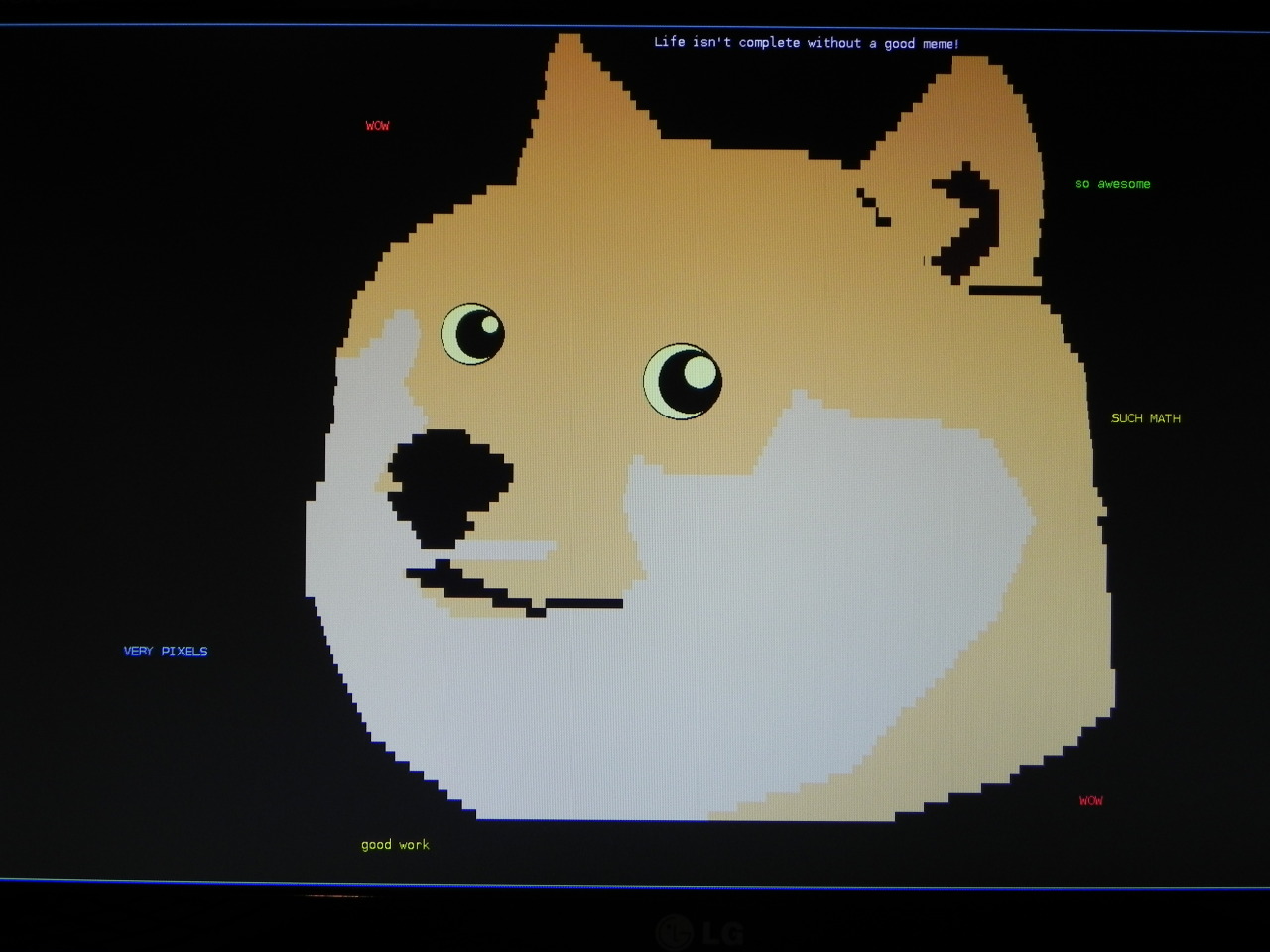
Finally, I wrote paint. Sort of. I added a peek and poke command to the OS, which allowed me to write to arbitrary addresses. Yes, I’m aware that this is considered very dangerous, but I didn’t know how to implement segmentation faults, or how to write the ethernet driver, so it didn’t matter.
I ended up implementing a little program that would let me draw things to the framebuffer. I could set the color and the tool. I could draw text, circles, lines, and rectangles. It turns out, it is really difficult to draw lines and circles, but luckily the Wikipedia articles on the matter are quite acceptable.
The final result;
Land Ho
This project was insane. If you are a little bit insane and really love low-level work, I would highly recommend doing this. I learned a ton about how things work. I strongly believe that this has only made me a better programmer, and at the very least, it’s a fun conversation starter.
- I really don’t have an issue with pointers anymore. After having to specify every load and store explicitly and then having to manually remember, even the raw pointers in C are an amazing improvement.
- I think I have a reasonably good grasp on how modern programming languages are compiled down into assembly, and then into machine instructions.
- Learned how colors work in the computer.
- Learned about endianness
- Learned assembly
In about the time of a month, I went from having a blinking light to being able to draw pictures with a command-line version of paint.